First Steps
Logging in
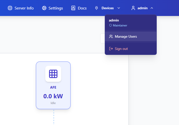
When the EMS4DC is started and accessed in a browser, you will need to log in using the default credentials: username: admin and password: admin. These credentials are automatically created during the installation phase. The maintainer of the system can change the password or username in the Manage Users tab, which can be found in the top right position of the HMI:
Configuring the assets and the site
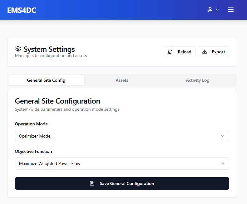
When the EMS4DC is installed, the energy assets will not be present in the configuration and it will be required to add them in the Settings page and configure their parameters as well as their Modbus TCP/IP communication parameters, such as addresses, endianness, etc. Moreover, in the Settings page it is needed to define the operation mode and the objective function of the optimizer.
General Site Config
At the beginning it is recommended to select Optimizer Mode, as it requires less configuration and fewer drivers.
Assets
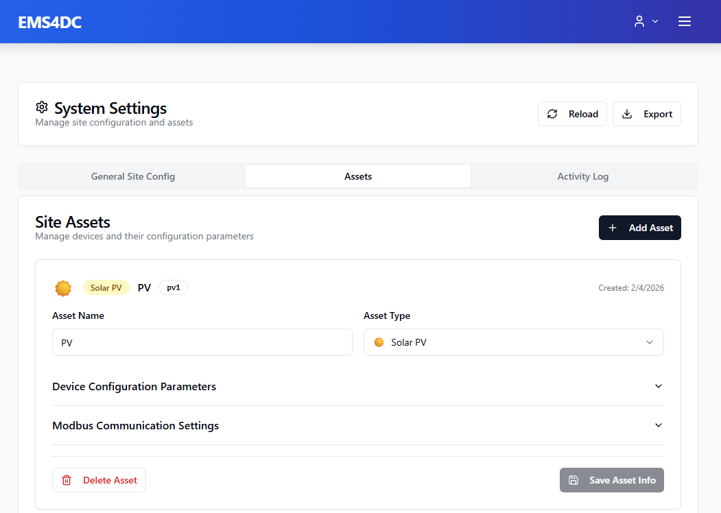
On the Settings page in the Assets tab, the maintainer can add the energy assets which are going to be used on the site via the + Add Asset button. As a Display Name it is recommended to use short names such as PV ROOF or LOAD OFFICE, so that assets are easily recognizable when there is more than one asset of the same type.
| Supported Type | Description |
|---|---|
| Solar PV | Electrical plant with photovoltaic panels |
| Battery Storage | Battery Energy Storage System (BESS) |
| Load | Any load which can be curtailed/shed during the optimization process. For example, lighting during the day. |
| Critical Load | The load which must not be curtailed during the optimization process. For example, a server's power supply. |
| Unidirectional EV charger | EV chargers which support only one way of energy flow (from grid to car) |
| Bidirectional EV charger | EV chargers that support bidirectional power flow, i.e. Vehicle to Grid (V2G) chargers |
| Wind Generator | Wind generator |
| Active Front End | Indicates the asset which connects the site to the main electrical grid. |
Device Configuration Parameters
For each of the added assets it is needed to provide the hardware parameters of the individual asset, such as nominal/maximum power, maximum current, etc. This can be done in the Device Configuration Parameters section.
Modbus Communication Settings
The Modbus Communication Settings section allows you to specify the registers which need to be read from or written to individual devices. For each type of asset there is a minimum required set of registers which must be provided in order for EMS4DC to work. The list of required read registers/values for each type of asset is provided below:
| Asset Type | Name in the Modbus Settings | Description | Unit |
|---|---|---|---|
| Solar PV | POWER | Power of the PV | Watts |
| Wind | POWER | Power of the wind generator | Watts |
| Battery Storage | POWER | Power of the Battery Energy Storage System | Watts |
| Battery Storage | SoC | State-of-Charge of the BESS | % |
| Active Front End | POWER | Power of the AC/DC point | Watts |
| Active Front End | AVBL | Availability of the AFE: 1 for available, 0 for not active | - |
| Active Front End | GRIDSRVC | Grid service amount of the AC/DC point | Watts |
| Load | POWER | Power of the load | Watts |
| Critical Load | POWER | Power of the critical load | Watts |
| Unidirectional EV charger | POWER | Power of the EV charger | Watts |
| Unidirectional EV charger | SoC | SoC of the car connected to the unidirectional EV charger in percent | % |
| Unidirectional EV charger | CAR_CAP | Capacity of the car connected to the unidirectional EV charger | Watt-Hours |
| Unidirectional EV charger | CAR_MAX_P | The maximum power the car can accept | Watts |
| Bidirectional EV charger | POWER | Power of the bidirectional EV charger | Watts |
| Bidirectional EV charger | SoC | SoC of the car connected to the bidirectional EV charger in percent | % |
| Bidirectional EV charger | CAR_CAP | Capacity of the battery of the car connected to the bidirectional EV charger | Watt-Hours |
| Bidirectional EV charger | CAR_MAX_P | Maximum power the car connected to the bidirectional EV charger can provide/accept | Watts |
| Bidirectional EV charger | CAR_AVBL | Parameter which indicates if the car can discharge at the moment: 1 if the car can provide power, 0 if not | - |
| Bidirectional EV charger | CAR_ARRIVAL | SoC of the car at the moment of arrival | % |
Modes
The EMS4DC supports two operational modes: Optimizer Mode and Droop Mode.
Optimizer Mode
In the Optimizer Mode the EMS4DC triggers an optimization process every 15 minutes and the outputs of the optimization are sent directly to the assets via Modbus TCP/IP. For this mode, it is needed to define Modbus Write parameters on the Settings page in the Assets tab. The list of required write registers is provided below:
| Asset Type | Name in the Modbus Settings | Description | Unit |
|---|---|---|---|
| Solar PV | POWER_SETPOINT | Optimizer decides how much PV power to utilise (curtailment setpoint) | Watts |
| Wind | POWER_SETPOINT | Optimizer decides how much wind power to utilise (curtailment setpoint) | Watts |
| Battery Storage | POWER_SETPOINT | Power setpoint for BESS; a positive value means the BESS will be requested to discharge, a negative value means charging | Watts |
| Battery Storage | LEVEL_SETPOINT | Battery level setpoint in Wh. The BESS will try to reach this level. | Watt-Hours |
| Active Front End | POWER_SETPOINT | Power setpoint for AFE; a positive value means the AFE will be requested to import power from the grid, a negative value means exporting power | Watts |
| Load | POWER_SETPOINT | Load power consumed (setpoint = allowed consumption limit) | Watts |
| Critical Load | POWER_SETPOINT | Load power consumed (setpoint = allowed consumption limit) | Watts |
| Unidirectional EV charger | POWER_SETPOINT | Power setpoint for the unidirectional EV charger | Watts |
| Unidirectional EV charger | SOC_TARGET | Target SoC for the car connected to the unidirectional EV charger in percent | % |
| Bidirectional EV charger | POWER_SETPOINT | Power setpoint for the bidirectional EV charger | Watts |
| Bidirectional EV charger | SOC_TARGET | Target SoC for the car connected to the bidirectional EV charger in percent | % |
Droop Mode
In the Droop Mode the EMS4DC triggers the optimization process the same way as in Optimizer Mode, however in Droop Mode the optimizer outputs are transformed to form a device-specific droop curve before sending the values to the device. For this mode, it is needed to write drivers for the assets.
Example Driver
The example driver will be shown for the Active Front End (AFE) developed during the SHIFT2DC project. The droop curve for this AFE is constructed via the following parameters:
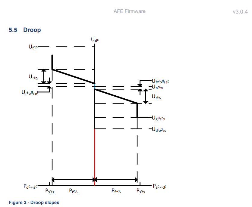
The intended use of EMS4DC is only in Normal Operation according to the Current OS consortium. This is why parameters such as Utrip, Uguard, and Udiodes are not considered in this example, as they lie outside the bounds of normal operation.
| Forming Parameter | Naming used in EMS4DC |
|---|---|
Ure_delta | RE_VOLT_DELTA |
Ure_offset | RE_VOLT_OFST |
Ufw_offset | FW_VOLT_OFST |
Ufw_delta | FW_VOLT_DELTA |
Pre_delta | RE_P_MAX |
Pfw_delta | FW_P_MAX |
V_offset | VOLT_OFST |

The main goal of the droop driver is to read the optimizer output and then construct the droop curve in the Current OS form and define the variables which are used by the asset to build the droop curve.
It is needed to create a separate driver file for each asset. For instance, for AFE it is needed to create core/drivers/afe1_driver.py and copy the contents of core/drivers/template_driver.py into afe1_driver.py.
The name of the driver can be anything, however it is strongly recommended to use the following format: {assetUniqueID}_driver.py. The assetUniqueID can be found on the Settings page in the Assets tab next to the asset's name. For AFE, afe1 will be used.
In afe1_driver.py there are multiple adjustments which need to be made:
- Give a unique name to the driver's class on
line 37. For instance,ActiveFrontEndDriver. - Optionally, adjust the comment block on
line 38. - Specify the
DEVICE_TYPEonline 44. For instance,"AFE".
| Supported Asset Type | DEVICE_TYPE String |
|---|---|
| Solar PV | "PV" |
| Battery Storage | "BESS" |
| Load | "LOAD" |
| Critical Load | "CRITICAL_LOAD" |
| Unidirectional EV charger | "UNI_EV" |
| Bidirectional EV charger | "BI_EV" |
| Active Front End | "AFE" |
| Wind Generator | "WIND" |
- In the
_load_device_config(self, asset_key: str = "assetUniqueID")function, provide theasset_keyof the asset, e.g."afe1". - On
line 102replace'assetUniqueID'with the actualassetUniqueID, e.g."afe1". - Adjust the
transform_droop_curve()function so that it provides the values for the registers used by the asset to construct the droop curve. Thetransform_droop_curve()function contains examples of how data can be extracted from the optimizer output or from the configuration parameters. - The format of the optimizer output has the following form:
{
    "obj": float,
    "imp": float, "exp": float, "exp1": float, "exp2": float,
    "afe":    { "<assetUniqueID>": { "imp", "exp", "exp1", "exp2" } },
    "pv":     { "<assetUniqueID>": { "power" } },
    "wind":   { "<assetUniqueID>": { "power" } },
    "load":   { "<assetUniqueID>": { "power" } },
    "cload":  { "<assetUniqueID>": { "power" } },
    "bess":   { "<assetUniqueID>": { "charge", "discharge", "level" } },
    "unidir": { "<assetUniqueID>": { "charge", "soc" } },
    "bidir":  { "<assetUniqueID>": { "charge", "discharge", "soc" } }
}
- Finally, map the variables to the asset's write registers, which were defined on the
Settingspage:
droop_curve_registers = {
    "FW_VOLT_OFST": fw_volt_ofst,
    "FW_VOLT_DELTA": fw_volt_delta,
    "RE_VOLT_OFST": re_volt_ofst,
    "RE_VOLT_DELTA": re_volt_delta,
    "VOLT_OFST": volt_ofst,
    "FW_P_MAX": fw_p_max,
    "RE_P_MAX": re_p_max
}
- Optionally, additional validation can be implemented in the
validate_setpoints()function. - To display the constructed droop curve, adjust
EMS4DC/web-app/frontend/src/pages/page-droop-curves.jsx. InLUT_DEFINITIONS, configure the device and its visualization in the following form:
afe1: {
    assetType: "AFE",
    assetKey: "afe1",
    axes: {
      x: { label: "Power", unit: "W" },
      y: { label: "Voltage", unit: "V" }
    },
    buildLUT: (modbusData) => {
      const FW_VOLT_OFST  = modbusData.afe1_FW_VOLT_OFST  || 0
      const FW_VOLT_DELTA = modbusData.afe1_FW_VOLT_DELTA || 0
      const FW_P_MAX      = modbusData.afe1_FW_P_MAX      || 0
      const RE_VOLT_OFST  = modbusData.afe1_RE_VOLT_OFST  || 0
      const RE_VOLT_DELTA = modbusData.afe1_RE_VOLT_DELTA || 0
      const RE_P_MAX      = modbusData.afe1_RE_P_MAX      || 0
      const VOLT_OFST     = modbusData.afe1_VOLT_OFST     || 0

      return [
        {
          index: 0,
          x: -FW_P_MAX,
          y: 700 + VOLT_OFST - FW_VOLT_OFST - FW_VOLT_DELTA,
          x_param: "-1 * FW_P_MAX",
          y_param: "700 + VOLT_OFST - FW_VOLT_OFST - FW_VOLT_DELTA"
        },
        {
          index: 1,
          x: 0,
          y: 700 + VOLT_OFST - FW_VOLT_OFST,
          x_param: "0",
          y_param: "700 + VOLT_OFST - FW_VOLT_OFST"
        },
        {
          index: 2,
          x: 0,
          y: 700 + VOLT_OFST + RE_VOLT_OFST,
          x_param: "0",
          y_param: "700 + VOLT_OFST + RE_VOLT_OFST"
        },
        {
          index: 3,
          x: RE_P_MAX,
          y: 700 + VOLT_OFST + RE_VOLT_OFST + RE_VOLT_DELTA,
          x_param: "RE_P_MAX",
          y_param: "700 + VOLT_OFST + RE_VOLT_OFST + RE_VOLT_DELTA"
        }
      ]
    },
    // Parameters needed from Modbus (without assetKey prefix)
    requiredParams: ["FW_VOLT_OFST", "FW_VOLT_DELTA", "FW_P_MAX", "RE_VOLT_OFST", "RE_VOLT_DELTA", "RE_P_MAX", "VOLT_OFST"]
  },